
Industry news
Root Causes and Solutions for Low FPC Peel Strength
2026-06-03
Throughout the TFT-LCD module manufacturing process, various methods are employed to evaluate performance. Failure to meet these performance criteria suggests that the product's service life and stability may fall short of expectations. Following the FOG (Film On Glass) bonding process, a peel strength test is typically conducted on the FPC to assess the adhesive performance between the FPC, ACF, and the LCD panel.
During the FPC peel strength test, a higher tensile value indicates better adhesion, thereby reducing the risk of issues with the LCD module. The following information regarding test conditions, sample requirements, calculation methods, and control standards is provided for your reference:
①Test Conditions: Peel angle at 90 degrees; Peel speed at 10 mm/min.
②Sample Requirements: Samples taken after FPC main bonding, but prior to adhesive sealing (potting).
③Calculation Formula: F = (P * 1000) / (W / 10) ;Where P represents the measured tensile force (unit: kg/cm), and W represents the length of the FPC bonding area (unit: mm).
④Control Standard: ≥ 700 g/f/cm.
***This article summarizes the six common causes of unsatisfactory FPC peel strength and their corresponding improvement countermeasures.
1. Bubbles Present After FOG Bonding
The presence of bubbles after FOG bonding is a very common phenomenon. However, FOG bubble defects need to be categorized. During the bonding process, bubbles are generally classified into two types: flow bubbles and delamination bubbles.
①Flow Bubbles: Flow bubbles occurring after FOG bonding are essentially "air pockets" within the ACF resin. They primarily form under non-vacuum conditions when air surrounding the electrodes is trapped into the ACF resin during the ACF laminating and main bonding processes.
Under bright-field microscopy, flow bubbles appear transparent in the center with thick, dark edges. They have a smooth appearance; smaller bubbles are nearly circular and do not exhibit growth (they do not expand over time). However, if flow bubbles are too large or excessive, they pose a risk of reducing FPC peel strength.
Improvement Measures: To address flow bubbles, the ACF laminating speed is typically optimized to ensure uniformity, preventing air entrapment caused by excessive speed. Additionally, the temperature, duration, and pressure during the FOG bonding process can be moderately increased.
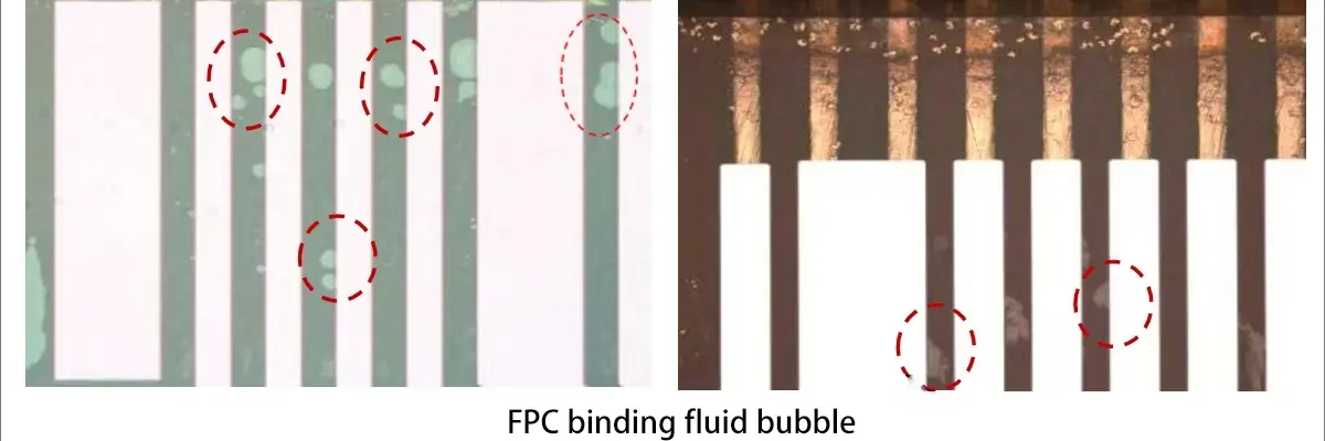
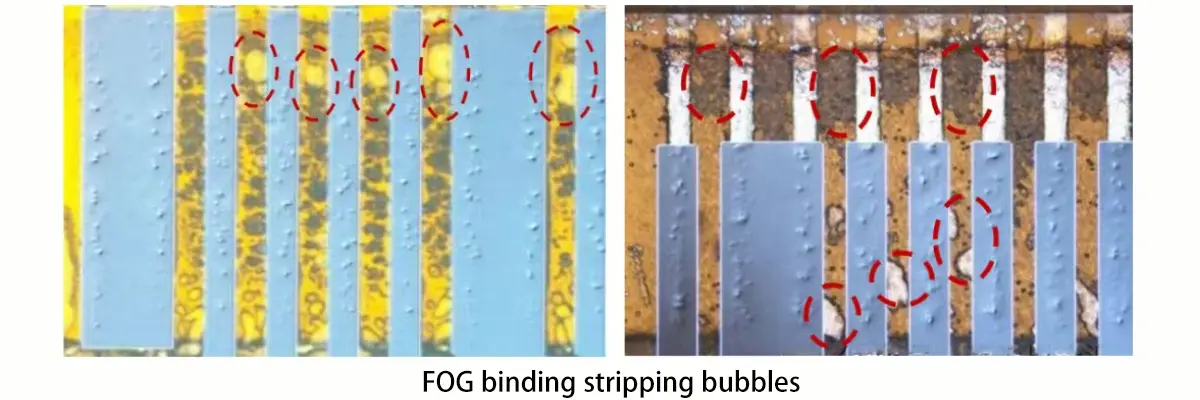
②Delamination Bubbles: The primary cause of delamination bubbles after FOG bonding is that, under high temperature and pressure, the cushion material compresses the gaps between the FPC electrodes, causing deformation of the FPC substrate. Once the main bonding process concludes, the FPC rebounds, pulling at the ACF resin. This ultimately results in delamination between the FPC and ACF, or between the ACF and the LCD glass substrate, leading to bubble defects.Delamination bubbles generally appear whitish or iridescent with indistinct edges. They are often irregular in shape and tend to grow larger over time. These bubbles are frequently accompanied by shallow impressions (light impressions), and they also reduce the FPC peel strength.
Improvement Measures: To address delamination bubbles, the bonding pressure during the FOG process is typically reduced. This minimizes the deformation of the FPC in the gaps between electrodes, thereby lowering the risk of delamination bubble formation.
2. Oxidation or Contamination on the FPC Gold Finger Surface
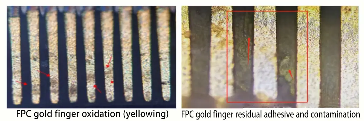
Oxidation of the FPC gold fingers is a very common defect. Once oxidized, bonding the FPC to the LCD can trigger numerous issues, such as increased contact resistance, shallow conductive particle impressions, and unsatisfactory peel strength between the FPC and LCD.
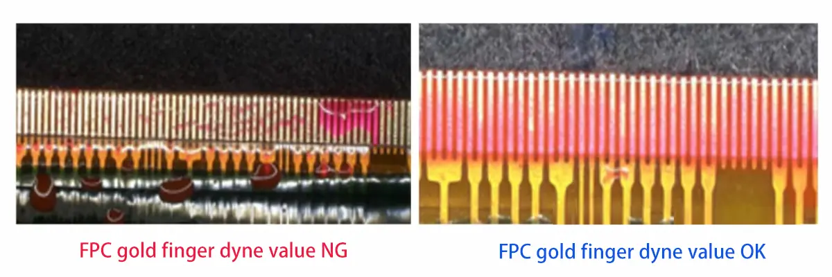
Surface contamination or residual adhesive on the FPC gold fingers will reduce the surface resistivity, consequently lowering the Dyne level (surface energy) of the gold fingers. Under these conditions, the risk of failing the FPC peel strength test becomes extremely high.
To address contamination and residual adhesive on the FPC gold finger surface, the current industry-standard approach is to process 100% of the FPC gold finger surfaces through Plasma treatment. Concurrently, the surface energy (Dyne level) of the gold fingers must be controlled, with a general recommendation of ≥ 32 Dyne.
3. Suboptimal FOG Bonding Parameters
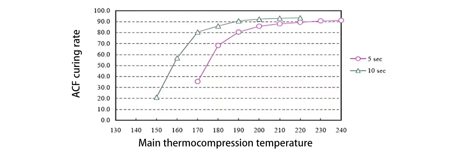
The conditions of the FOG main bonding process also impact the FPC peel strength, specifically reflected in the ACF curing rate and theparallelism of the bonding head.
Under normal circumstances, the FOG ACF curing rate is required to be ≥ 80%. Insufficient curing rate will reduce the bonding reliability between the FPC and LCD, ultimately resulting in unsatisfactory peel strength.
The parallelism of the bonding head indicates the uniformity of pressure applied to the FPC and LCD. If the bonding head parallelism does not meet specifications, it means the pressure applied during the FOG main bonding process is uneven. This ultimately leads to shallow impressions in localized areas of the FOG bonding pads and results in unsatisfactory FPC peel strength.
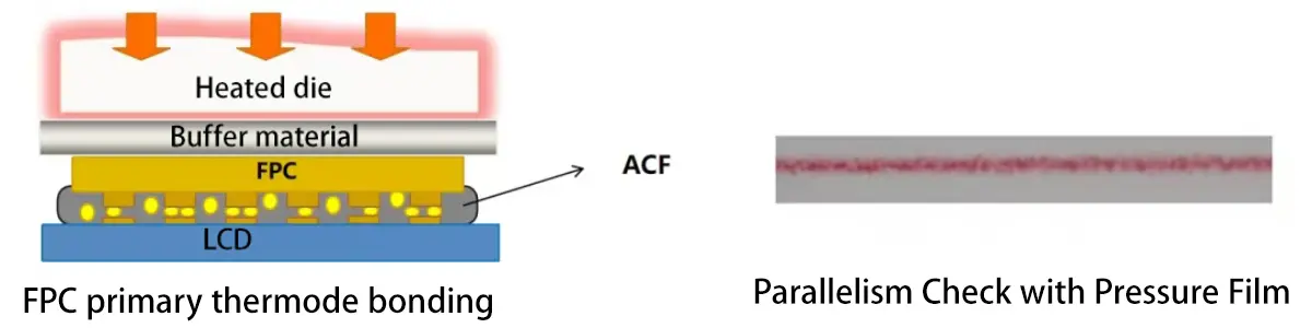
To address the ACF curing rate issue, the FOG main bonding temperature and time can be moderately increased within the recommended ACF parameters. For example, raising the settings from 160°C/8s to 165°C/10s. This adjustment enhances the ACF curing rate, thereby improving the FPC peel strength.
Regarding the parallelism of the FOG bonding head, pressure-sensitive paper (e.g., Fuji Presscale) should be used to inspect and verify the parallelism according to established requirements. This procedure prevents localized non-conformances (NG) in parallelism, ensuring that localized weak points in FPC peel strength are avoided.
4. Insufficient Contact Area Between FPC Gold Fingers and LCD Pads
To achieve a narrower bottom bezel (D-Border) on TFT-LCD panels, shortening the length of the FPC bonding pads on the LCD is an inevitable design choice.
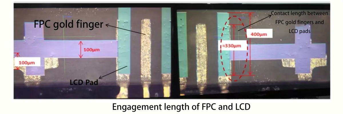
However, when the pad length on the LCD is reduced, the length of the FPC gold fingers is correspondingly shortened. This results in a smaller effective contact area between the FPC gold fingers and the LCD pads, thereby increasing the risk of failing the peel strength test.
Based on validation data from our work, under identical conditions, a design with an overlap length of 0.33mm exhibits approximately 23% lower peel strength compared to a 0.4mm overlap. This reduction causes the result to fall below the standard of ≥700 g/f/cm.
The effective contact area affects not only the peel strength but also the number of conductive particles per gold finger, increasing the risk of insufficient particle count.
To balance the requirements for a narrow D-Border and the risks of peel strength/particle count failures, it is recommended that the contact length between the FPC gold fingers and LCD pads be ≥ 0.35mm.
5. FPC Alignment Mark Located Too Far from the Outline
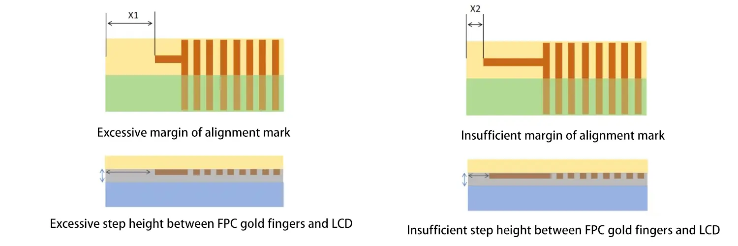
On the LCD panel, alignment marks are designed on the leftmost and rightmost sides of the FPC bonding pads. Correspondingly, the FPC gold fingers also feature alignment marks on both ends to match those on the LCD. These marks are used to enhance the bonding alignment accuracy between the FPC and the LCD.
While the marks on the LCD are fixed, the marks on the FPC are adjustable (within the constraint of matching the LCD marks). If the FPC alignment marks are positioned too far from the FPC outline, the lack of support from the alignment marks can result in a significant step difference (height disparity) between the FPC and LCD at the left and right edges. This increases the risk of failing the peel strength test at these locations.
Therefore, when designing the FPC alignment marks, it is generally recommended to position the edge of the alignment mark 0.5 to 1.0mm away from the edge of the FPC outline to ensure adequate peel strength.
6. Non-compliant ACF Storage and Temperature Recovery
Standardized management and handling of ACF is a critical process in display module manufacturing, given the high importance of ACF in these modules.
①ACF Storage:
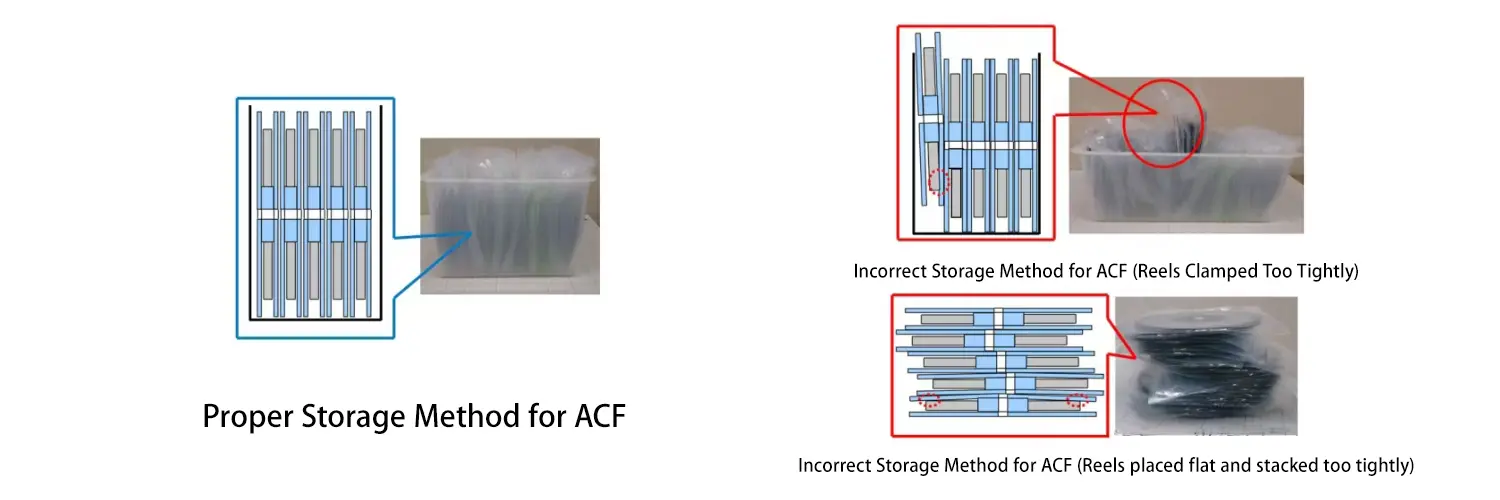
ACF is typically supplied in reel format and stored in vacuum-sealed antistatic bags within a low-temperature environment of -10°C to 5°C. The reels must be stored vertically. Ensure that vertically stored reels are not packed too tightly together, as this can lead to uneven temperature distribution. It is strictly prohibited to store ACF reels horizontally or to stack them on top of one another. The primary purpose of this rule is to prevent the ACF roll from loosening or deforming, which would adversely affect its performance.
②ACF Temperature Recovery (Thawing):
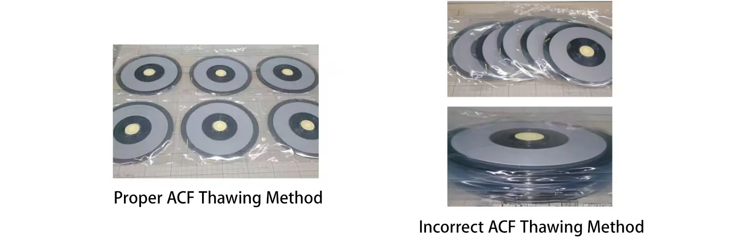
ACF cannot be used immediately upon removal from cold storage. It must be allowed to return to room temperature. This is necessary to ensure that the temperature conducted to the ACF resin during bonding meets the required specifications. Furthermore, ACF taken directly from cold storage cannot adhere properly to the LCD glass substrate.Additionally, packaging bags removed from cold storage will have condensation (moisture) on them. The bags must be left untouched until this surface moisture fully evaporates before opening.The ACF temperature recovery process has the following key requirements:
●Do not stack ACF reels; they must be placed flat and individually to allow even warming.
●Keep the packaging sealed and allow it to recover at cleanroom temperature (25°C) for 1 hour.
●If surface moisture is still present on the packaging bag after the initial 1-hour recovery, leave it for another hour to ensure all moisture has completely dissipated before use.
The purpose of proper ACF storage and temperature recovery is to prevent premature reaction of the curing agent within the ACF resin. This ensures the bonding adhesion and performance between the ACF, FPC, and LCD, ultimately guaranteeing that the FPC peel strength meets the required specifications.